
Laser Alignment Services
The Ultimate Guide to Laser Shaft Alignment Services: Methods, Tolerances & Thermal Growth
Industrial rotating machinery relies on co-axial shaft centerlines to transfer torque smoothly from driver to driven unit. Over 50% of premature machine breakdowns in manufacturing, MEP pump stations, and oil & gas plants stem directly from shaft coupling misalignment.
Transitioning from legacy straight-edge and dial indicator methods to dual-laser alignment systems enables plant engineers to achieve sub-millimeter precision, eliminate soft-foot errors, and extend machinery mean time between failures (MTBF).
Types of Shaft Misalignment & Machinery Failure Modes
Before executing laser measurements, technicians evaluate coupled machinery for horizontal, vertical, and angular offset errors.
Primary Misalignment Conditions:
- Parallel (Radial) Misalignment: Shaft centerlines run parallel to each other but are offset distance-wise horizontally or vertically.
- Angular Misalignment: Shaft centerlines meet at an angle rather than forming a single straight line, creating uneven gap spacing across coupling faces.
- Combination Misalignment: The most common field condition, where coupled shafts exhibit both parallel offset and angular gap variations simultaneously.
The Laser Shaft Alignment Procedure & Measurement Protocol
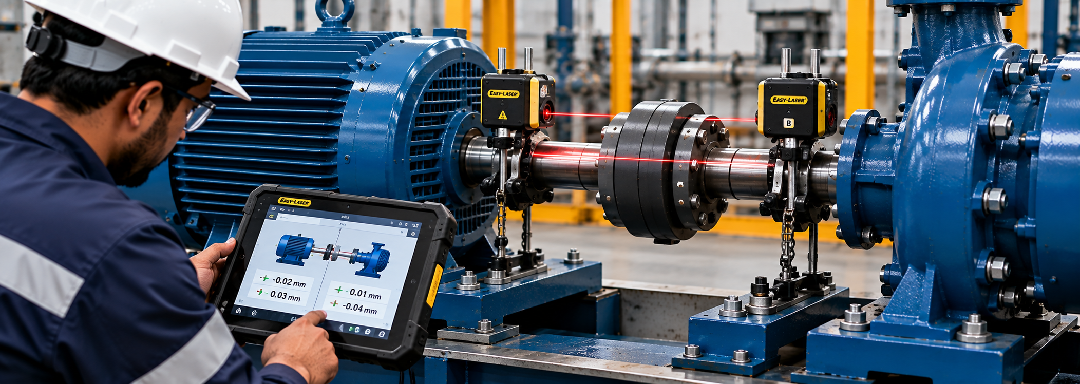
Modern laser alignment tools utilize dual semiconductor laser diodes paired with digital Position Sensitive Detectors (PSD) to calculate real-time movement vectors.
Step-by-Step Alignment Execution:
- Pre-Alignment Inspection: Inspecting shaft runout, cleaning mounting feet, and removing burrs from baseplate surfaces.
- Soft-Foot Correction: Checking each motor foot using digital feeler gauges or laser soft-foot routines to eliminate structural frame distortion before tightening anchor bolts.
- Laser Sensor Mounting: Clamping V-bracket sensor units onto the driver and driven shafts or coupling hubs.
- Three-Point Sweep (9-12-3 Method): Rotating shafts through 180 degrees to capture precise co-axial coordinates across vertical and horizontal planes.
- Shim Adjustment & Horizontal Move: Adding or removing precision stainless steel shims under mounting feet for vertical correction, followed by horizontal jacking bolt adjustments.
Thermal Growth Expansion & Dynamic Target Calculation
Machinery aligned at ambient room temperature shifts position once operating temperatures stabilize. Hot pumps, steam turbines, and large electric motors undergo thermal expansion ($\Delta L = L \cdot \alpha \cdot \Delta T$).
Technicians input thermal expansion coefficients ($\alpha$), distance dimensions ($L$), and operational delta temperatures ($\Delta T$) into laser alignment computers to set precise cold-alignment offsets. This ensures perfect shaft co-axiality when equipment reaches full load.
Alignment Standards & Tolerance Reference Matrix
Laser alignment measurements are evaluated against standard rotational speed tolerances (ISO / ANSI standards).
| Rotational Speed (RPM) | Excellent Tolerance (Offset / Angular) | Acceptable Tolerance (Offset / Angular) | Action Required Threshold |
| 0 – 750 RPM | $0.12 \text{ mm} \ / \ 0.09 \text{ mm/100mm}$ | $0.18 \text{ mm} \ / \ 0.15 \text{ mm/100mm}$ | $> 0.25 \text{ mm}$ |
| 750 – 1500 RPM | $0.07 \text{ mm} \ / \ 0.06 \text{ mm/100mm}$ | $0.10 \text{ mm} \ / \ 0.10 \text{ mm/100mm}$ | $> 0.15 \text{ mm}$ |
| 1500 – 3000 RPM | $0.04 \text{ mm} \ / \ 0.03 \text{ mm/100mm}$ | $0.07 \text{ mm} \ / \ 0.05 \text{ mm/100mm}$ | $> 0.10 \text{ mm}$ |
| 3000 – 6000 RPM | $0.02 \text{ mm} \ / \ 0.02 \text{ mm/100mm}$ | $0.04 \text{ mm} \ / \ 0.03 \text{ mm/100mm}$ | $> 0.06 \text{ mm}$ |