
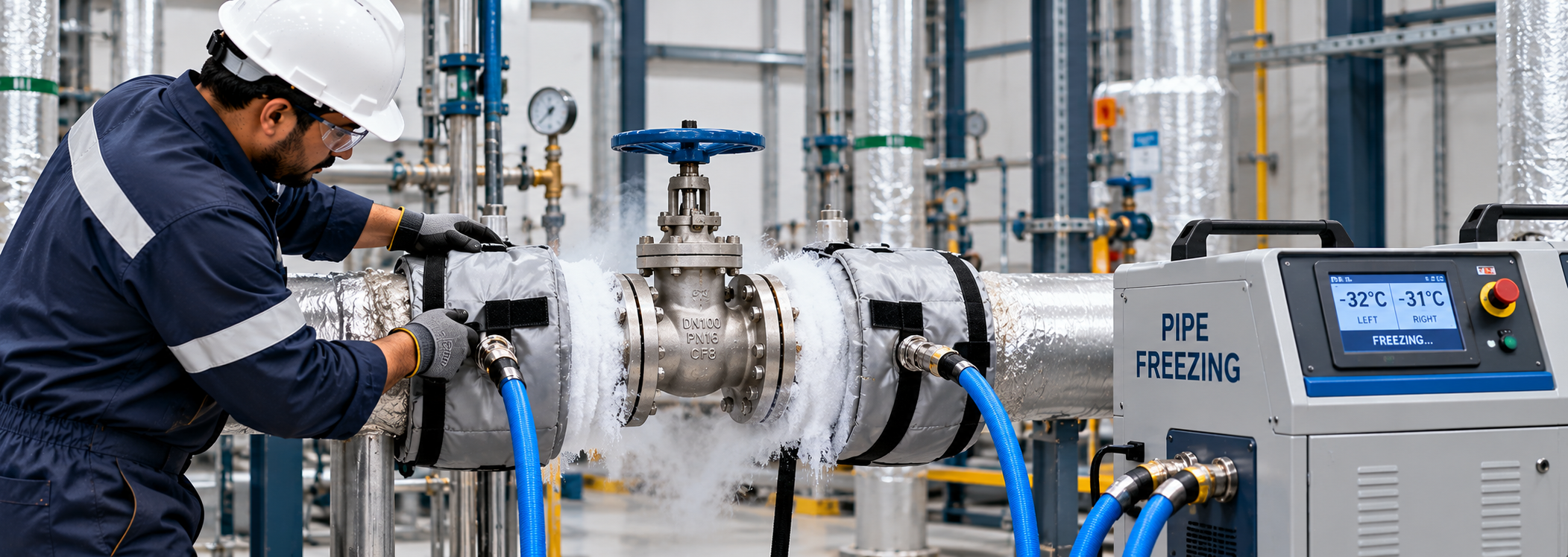
Pipe Freezing for Valve Replacement
The Ultimate Guide to Pipe Freezing for Valve Replacement & Line Isolation
Draining thousands of gallons of treated water, glycol, or process fluid from commercial HVAC systems or industrial plant piping creates immense operational delay, costly chemical refilling expense, and system re-commissioning downtime. Cryogenic pipe freezing services provide a safe, non-destructive isolation method by applying liquid nitrogen ($LN_2$) or solid carbon dioxide ($CO_2$) to establish a high-pressure solid ice plug directly inside the pipe.
This temporary freeze plug holds system pressure up to 200 bar (3,000 PSI), allowing mechanical technicians to cut line segments and replace isolation valves with zero fluid drain-down.
Cryogenic Isolation Equipment & Freeze Jacket Setup
Precision pipe freezing uses controlled freeze jackets fitted around carbon steel, copper, stainless steel, or ductile iron piping.
Key System Components:
- Specially Engineered Freeze Jackets: Sealed aluminum or stainless steel jackets clamped directly upstream and downstream of the targeted valve replacement zone.
- Liquid Nitrogen ($LN_2$) Delivery System: Injects liquid nitrogen at $-196^\circ\text{C}$ ($-320^\circ\text{F}$) around the outer pipe wall, rapidly drawing latent heat from stationary internal fluid.
- Temperature Monitoring Sensors: Surface thermocouples track thermal drawdown profiles to verify solid ice core formation before line opening.
Controlled Ice Plug Formation & Hydrostatic Hold Protocols
To guarantee technician safety when unbolting flanged valves or cutting pipe spools, the freeze plug must form a solid structural bond with the interior pipe wall.
Freezing Execution Sequence:
- Flow Verification: System pumps are isolated or bypassed to ensure absolute zero fluid velocity inside the freeze zone.
- Cryogenic Injection: Controlled $LN_2$ dosing forms radial ice growth from the inner pipe wall inward toward the center axis.
- Pressure Hold Verification: Once temperature sensors confirm $-30^\circ\text{C}$ to $-50^\circ\text{C}$ outer wall temperatures, technicians depressurize the downstream isolation zone to verify 100% bubble-tight sealing.
Valve Removal, Pipe Modification & Welding Considerations
Once the solid ice plug is holding full line pressure, technicians perform valve unbolting, flange refacing, or pipe welding work.
Safety & Integrity Guidelines:
- Minimum Distance Buffer: Hot work, TIG/SMAW welding, or flame cutting must occur at a safe distance (typically 3 to 5 pipe diameters) from the freeze jacket to prevent thermal degradation of the ice plug.
- Continuous Nitrogen Monitoring: Automatic $LN_2$ replenishment controllers maintain cryogenic levels throughout the entire duration of the valve installation.
Controlled Thawing & System Re-Commissioning
Following final torque-tightening of new valve flange bolts or non-destructive testing (NDT) of weld seams, the cryogenic delivery is stopped to begin controlled defrosting.
Natural ambient thawing prevents sudden thermal shock to the pipe material metallurgy. The temporary ice plug melts completely into the fluid stream without introducing foreign contaminants, chemicals, or atmospheric oxygen into closed-loop chilled water systems.
| Operational Parameter | Cryogenic Pipe Freezing | Hot Tapping & Line Stopping | Complete System Drain-Down |
| System Down-Time | 2 – 6 Hours | 6 – 12 Hours | 24 – 72 Hours |
| Fluid Loss / Refill Cost | Zero Fluid Loss | Minor Coupon Loss | 100% Fluid / Chemical Waste |
| Pipe Modification | Non-Intrusive (No Welding) | Intrusive (Welded Branch Saddle) | None |
| Pressure Hold Capacity | Up to 200 bar (3,000 PSI) | Up to 100 bar (1,450 PSI) | 0 bar (De-pressurized) |
| Pipe Diameter Range | 1/2″ to 36″+ ID | 2″ to 48″+ ID | All Sizes |